I've been working on another SquishBox PCB revision that's been cooking in my mind for a while. The basic idea started with something pretty mundane: I got tired of connecting jacks, buttons, and rotary encoders to the PCB with flying wires. It works, but it's time-consuming to assemble and doesn't make for a particularly sturdy piece of hardware.
When I open up other commercial hardware, I keep seeing a much nicer approach: the jacks and switches are soldered directly to the PCB, and then their physical mounting in the enclosure also holds the PCB in place. No fiddly 3D-printed brackets, no little mounting tabs that eventually tear off, and no extra standoffs or screws unless they're actually necessary. I wanted the SquishBox to work more like that.
Losing the Stomp Switch
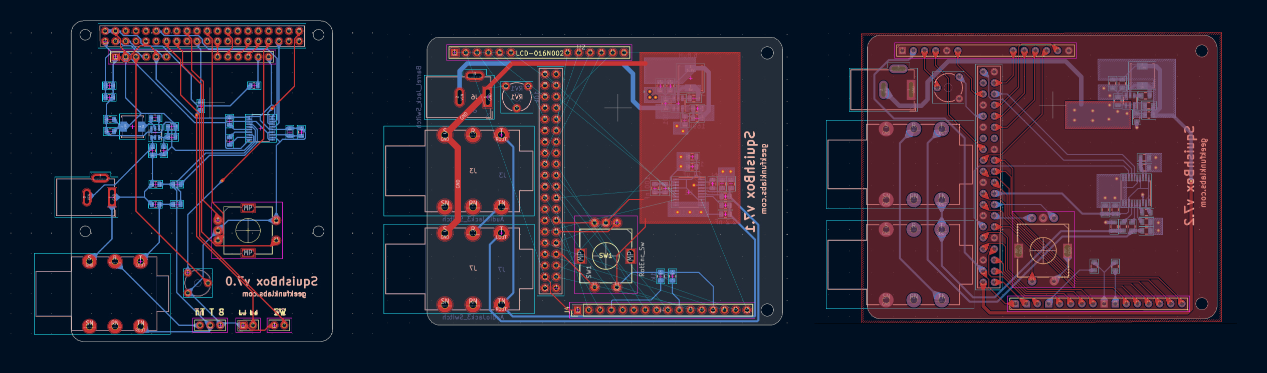
My first thought was to make the PCB roughly the same footprint as a Raspberry Pi 3/4, with the rotary encoder, DC jack, and audio jack mounted directly on the board. That worked reasonably well, but I couldn't find a good way to fit two audio jacks without running into the Pi. I also went looking for PCB-mount momentary stomp switches and couldn't find anything that really worked for the design. That led to a more interesting realization: the SquishBox doesn't actually need a stomp switch.
The rotary encoder is enough to navigate patches and menus, and the stomp switch has always been an optional control rather than something fundamental to the instrument. Making it optional simplifies the hardware considerably and lets the enclosure be used in different ways.
Rotating the PCB
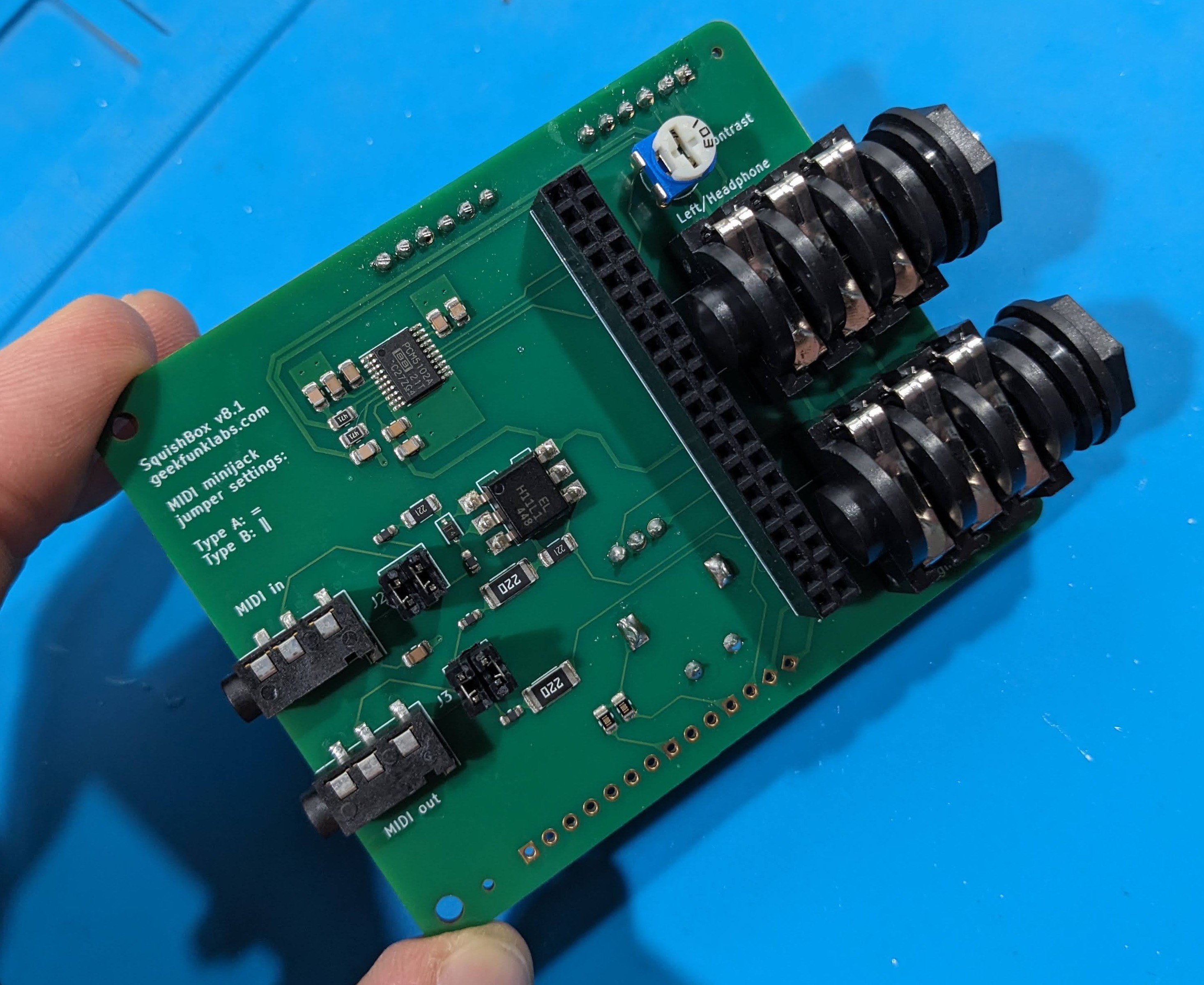
I still wasn't particularly happy with that first design, though, so I went back to the physical hardware and started playing around with a Raspberry Pi, loose components, and some paper cutouts. That led to a much better arrangement: instead of sitting directly on top of the Pi, the PCB is rotated 90 degrees, essentially making a little sideways hat that hangs off the edge of the Raspberry Pi.
That simple change solves a bunch of problems at once. The Pi's USB ports can stick out the back of the enclosure, where cables are less likely to get in the way, while the rest of the Pi's ports remain accessible from the side. The overhanging part of the PCB gives me enough room for two audio jacks, and also provides a convenient place for the LCD contrast adjustment. The encoder and audio jacks themselves can hold the PCB in position, eliminating most of the additional mechanical hardware I had been using. Best of all, the resulting SquishBox is actually a little more compact than the current version.
Working through these revisions also taught me something about PCB design that I had initially gotten wrong. I'd encountered some noise and hum in earlier versions and had assumed I was mostly dealing with ground-loop problems. Looking more carefully at the board design made me realize that I really do need substantial ground planes and much wider traces for the power and audio connections. The larger copper areas make a surprisingly big difference in keeping the sensitive audio circuitry happy.
There was a catch, naturally. Those big copper planes are also extremely good at carrying heat away from the soldering iron, which makes soldering components connected to them rather unpleasant. I had to learn about thermal reliefs in KiCad so that the ground pads could actually be soldered without spending ten minutes heating up the entire PCB.
That got me to version 7.2, which was a pretty successful design. It was straightforward to assemble, sounded good, and had some nice expansion features: the spare GPIO pins, along with 5V, 3.3V, and ground, are broken out along the edge of the board for easy access. I even added a couple of GPIO connections with built-in 1K resistors for driving LEDs.
Finally MIDI Jacks
Then I started thinking about MIDI. I've been seeing more and more modern hardware using 3.5mm TRS jacks for MIDI, including a lot of gear at KnobCon and in the new equipment I've been looking at online. Those connectors fit quite nicely on the SquishBox PCB, and adding MIDI input and output seemed like a much more useful way to spend the available space than continuing to dedicate it to a DC power jack.
This led to another question: does the SquishBox PCB need a power input at all? The Raspberry Pi is already sitting there providing the 5V power the SquishBox electronics need. If someone already has a suitable Pi power supply, why should I make them buy another power supply and a DC jack just for the SquishBox? And why should every user have to pay for an onboard switching regulator and all of its associated components if they don't actually need one?
So I've decided to let the user bring their own power. If someone wants to put a SquishBox on a 9V pedalboard, there are inexpensive 5V converters available for exactly that purpose. For everyone else, the Pi's normal power supply can do the job.
The resulting version 8 PCB removes the onboard regulator and DC jack and adds 3.5mm TRS MIDI input and output, including the necessary optocoupler and MIDI interface circuitry. I've also added jumper settings so the jacks can be configured for either of the two common TRS-MIDI wiring standards. That makes the SquishBox a considerably more useful piece of MIDI hardware without forcing everyone to pay for features they may not need.
This is turning into a fairly substantial redesign. The enclosure is changing, the power arrangement is changing, MIDI is being added, and the software will need some corresponding changes. But I think it's moving the SquishBox in a good direction: simpler, sturdier, more compact, easier to assemble, and more versatile.
That's been a recurring theme with this project. Every time I think I'm just making a small improvement, I discover that some underlying part of the design could be considerably better if I step back and rethink it. Version 8 is the result of doing that a few times in succession.