SquishBox PCB Update
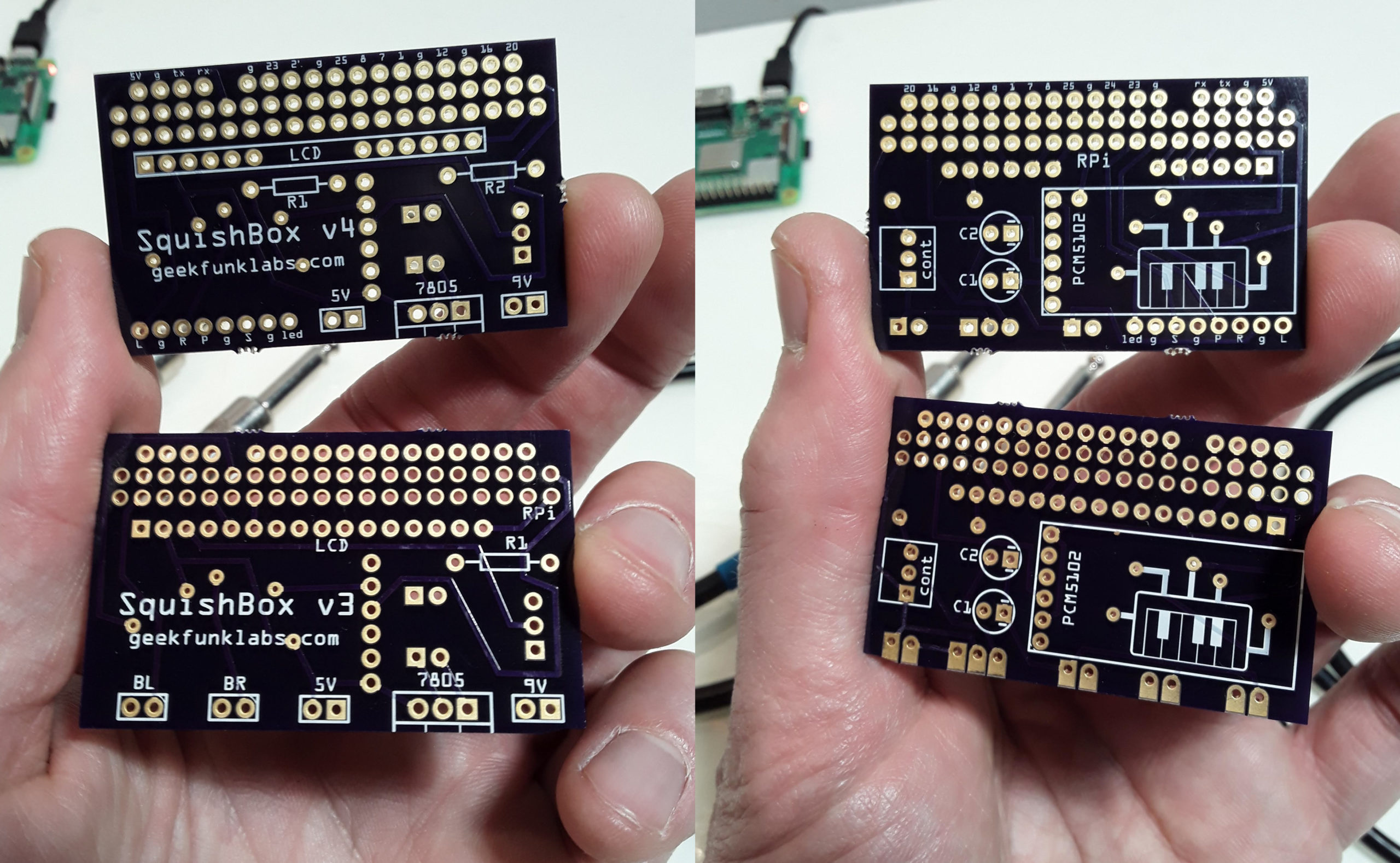
I’ve been working on an update to the SquishBox that uses a rotary encoder instead of two buttons to switch patches, open menus, etc. One stompbutton remains, but is instead sends a MIDI message that can be routed to any function desired depending on the patch/bank settings. I’ve also added a status LED that can be switched on/off by a router rule. I’ve modified the PCB with a row of pads to allow these connections. The picture above shows my last v3 PCB alongside the newer version. I’ll be updating the assembly instructions to reflect the new PCB, and the newer version of the SquishBox will be available in the Tindie store soon. The pinout of the new input bus is:
| Pin | GPIO | Description |
| L | 2 | left rotary encoder pin |
| g | ground for rotary encoder | |
| R | 3 | right rotary encoder pin |
| P | 27 | pushbutton for the rotary encoder |
| g | ground for the stompswitch | |
| S | 22 | stompswitch input |
| g | LED cathode pin | |
| led | 10 | LED anode pin (connected through R1 resistor) |
Since the input pins are connected to GPIO, the PCB can still be used to build a SquishBox with two left and right stompswitches, as long as the BTN_L and BTN_R values are set to the correct GPIO in hw_overlay.py.
The new PCBs are also available direct from OSHPark.
can I receive an update when the new boxes are ready for order
Sure! I will send you an email. You can also sign up on the waitlist on the product page in the Tindie store (in case I forget :-P)